KDPC-101

Product Code:KDPC-108
PROCESS CONTROL & INSTRUMENTATION LAB
Engineering and educational laboratory equipment from K. D. Engineers.
PRODUCT DETAILS
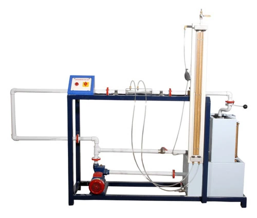
The setup consists of a process tank in which compressedair enters through a Pneumatic control valve. Thepressure transmitter is fitted on the process tank. The airpressure in process tank is sensed by the transmitter andcommunicated to the digital indicating controller. Thismeasured variable is compared with the set Point bycontroller and output is generated and given to I/Pconverter, which in turn supply the 3-15 Psig pressure tovary the opening of the Pneumatic control valve toeliminate the error observed. As the opening ofpneumatic control valve varies, the pressure in the Process Tank gets affected. This process goes on until the Set Point target is achieved. A ball valve is also providedin the process tank to disturb the system and to observethe effect of disturbance. These units along withnecessary piping are supported in a well-designedhousing and are fixed on base plate. The processparameter is controlled through computer by microprocessor Controller (SCADA Model) by manipulating thepressure in process tank.The present set-up is completely computerizedcontrolled. The Digital Indicating Controller have a facilityto interface the system with computer which enables tochange the PID parameters using computer. Theeducational software and data-logging package has beendeveloped for unit. The software environment base is of Labview of NATIONAL INSTRUMENTS, USA. This softwareis compatible to interfacing unit. This software package provides acomprehensive educational software environment withinwhich the PID investigations can be performed. Thissoftware is capable to tabulate the sample readingsaccording to the requirement of experiment under studyand results obtained can be compared. The real time dataacquisition can be done by interfacing the set-up withcomputer using software. This software can be usedoutside the laboratory with the computer to familiarizethe students with the equipment and procedures withthe help of Flow Diagrams provided in the software. Inflow diagrams Set Point, Process Variable and Controllers Output are visible on the screen and this data can betransferred in Excel Files for further calculations, plottinggraphs etc. Software allows the user to have control onsampling time, data logging, printing the stored data.